Isaac Occhipinti, Head of External Affairs at the Hot Water Association, takes a look at the two most common challenges when installing a hot water cylinder.
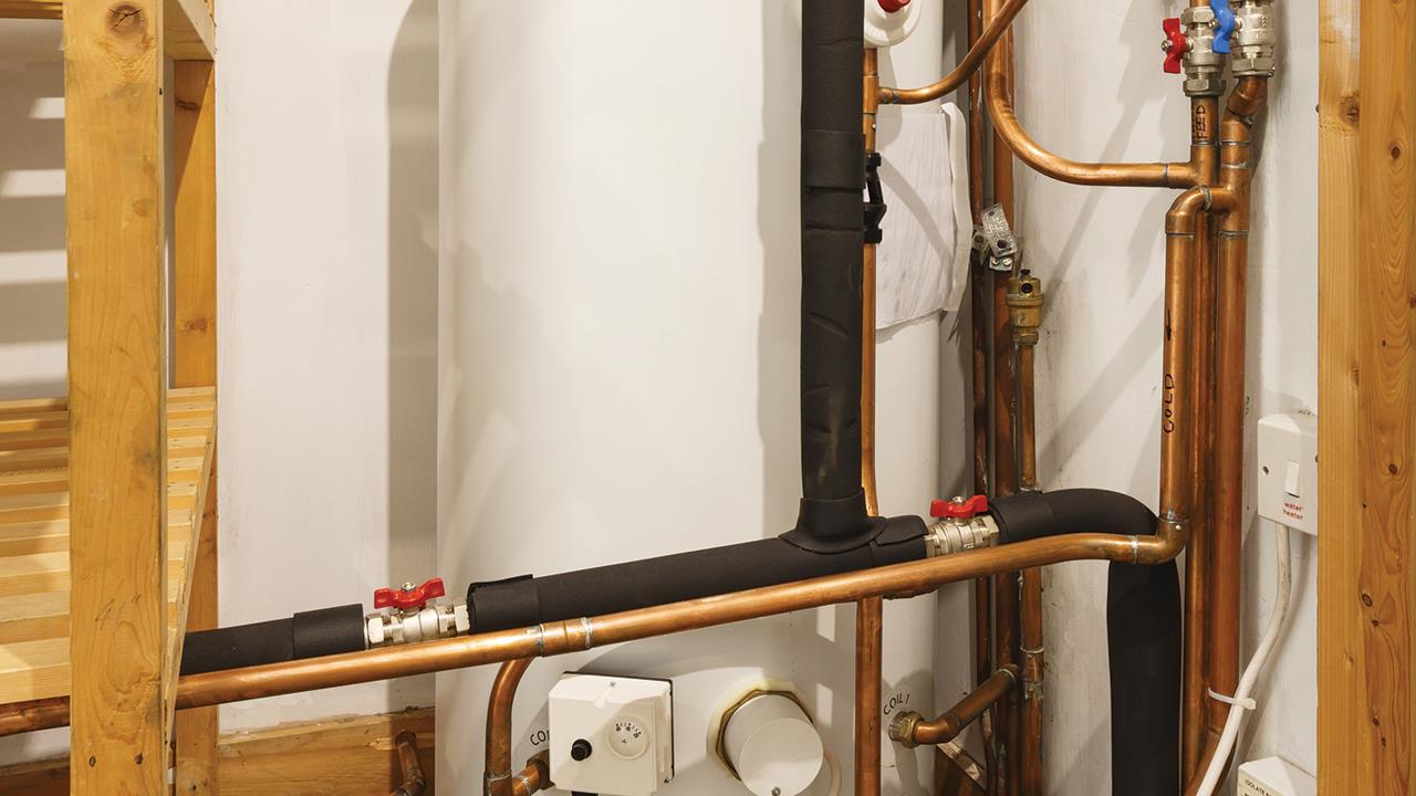
There are two main installation issues with unvented cylinders. The first usually comes down to space, which is a familiar challenge in any home. Not only does the size of the cylinder need to be considered, but also where any ancillary equipment is to be installed, such as external expansion vessels.
Industry standard has generally been a cylinder with a separate, wall-mounted expansion vessel. The system works, and is reliable, but it takes up space in a cylinder cupboard that could otherwise be used for storage.
By contrast the ‘bubble top’, or ‘air gap’ system, dispenses with the need for a separate expansion vessel. The system works by having a bubble of air trapped in the top of the cylinder, and the hot water drawn from the unit from a side or top mounted internal pipe that reaches into the water. The air gap is often kept separate from the water by a plastic floating baffle that sits on the water and moves vertically with the expansion of the water according to heat.
The air gap should be regenerated annually when the unit is serviced by an approved installer, thus preventing a loss of gap that would otherwise result in over-pressurisation of the cylinder and an operational discharge from the expansion relief valve.
Cylinders are also available with an ‘all on top’ design, with heating coil, hot and cold water services, safety valves, and expansion vessels all concealed and contained under a removable lid. This minimises the impact of external pipework and connections and optimises usable space.
In addition, there are slimline products available to fit into specific areas, as older open vented cylinder cupboards are often narrower than today’s cupboards – these are usually less than 500mm in diameter.
A further consideration could be two small vertical cylinders side by side as an option, which will allow 250-300l of water to be housed in a space about 1m high.
Manufacturers can offer specific advice to engineers and customers on designing an installation of this type, including schematic diagrams on series and parallel installations. Series installations will maximise the amount of usable hot water before it runs cold, and parallel installations will enhance the flow rate as long as you have got enough flow from the mains. In both cases, one cylinder can be switched off to reduce heat losses and energy usage if a smaller amount of domestic hot water use is anticipated.
Stay regulation compliant
A close second to space constraints is compliance with Building Regulations. Approved Document Part G covers sanitation, hot water safety, and water efficiency. A common oversight is the termination of the temperature and pressure relief discharge pipe. Part G3 3.62 specifies that the D2 discharge pipe should terminate as follows:
Water leaving the pipe could potentially be 100°C, so obviously is not safe to discharge into the home. Even after travelling from the unvented cylinder in the pipework, assuming that the length of the pipework has been calculated and installed correctly, the water could still be 80°C.
In addition to the top two challenges, the following considerations should also be made before installation:
In addition, following installation, the system should be fully commissioned and the operation explained to the homeowner. The engineer must provide a ‘commissioning certificate’, e.g. a Benchmark log book, to demonstrate this procedure has been carried out. The engineer’s details should also be filled out on the label applied to the cylinder.
If you'd like to keep up-to-date with the latest developments in the heating and plumbing industry, why not subscribe to our weekly newsletters? Just click the button below and you can ensure all the latest industry news and new product information lands in your inbox every week.
Subscribe to receive your free copy of HVP every month.